Baja Suspension System
Northwestern Baja 2024-2025 Vehicle
Suspension Lead
Led a 14-member team to design and fabricate the full suspension and brakes subsystem, using Lotus Shark and Optimum Kinematics to achieve neutral Ackermann, minimal bump steer, and a 4ft reduction in turning radius.
Skills: System Integration, SolidWorks CAD/FEA, Siemens NX CAM, Leadership, Offroad Suspension
Overview
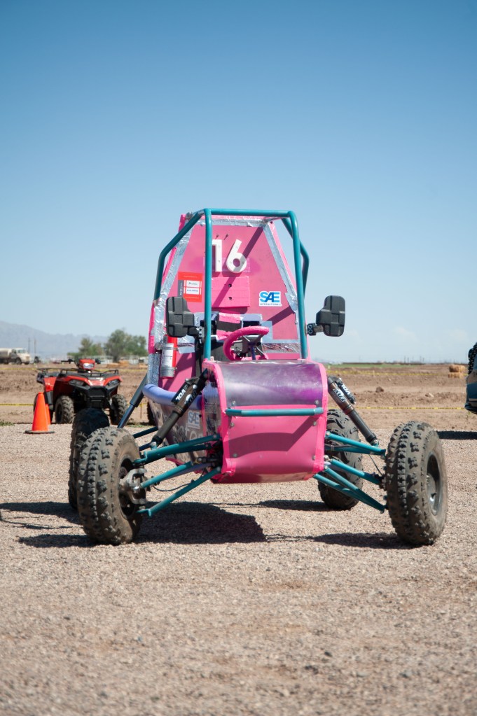
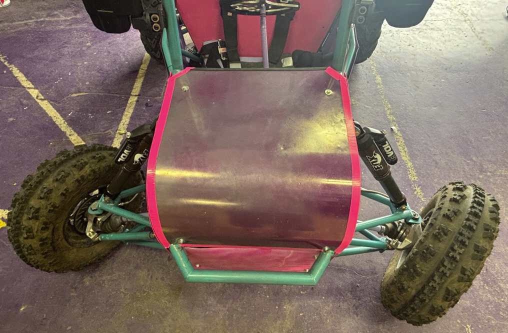
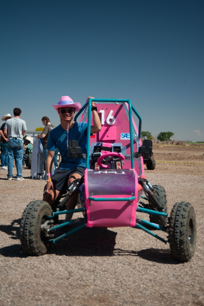
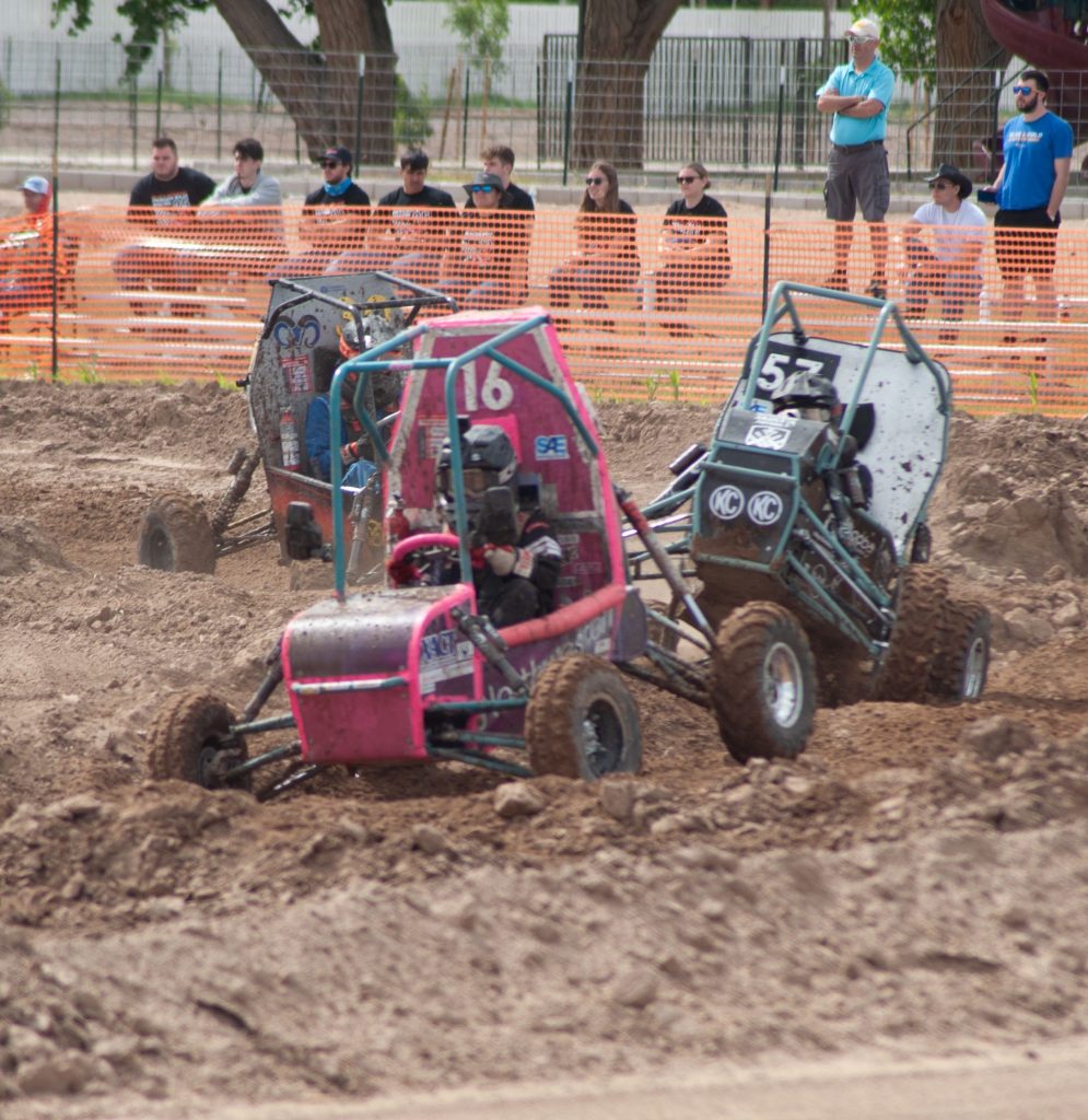
Every year, the Northwestern University Baja team designs and builds a custom offroad vehicle as part of the Baja SAE national collegiate competition series. The car is completely designed by students around a stock engine, and almost everything is made in-house at Northwestern University.
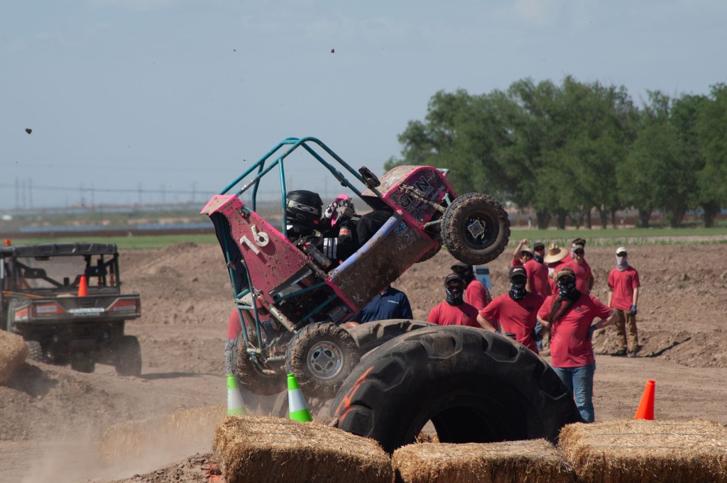
The competition is centered around events aimed to test our vehicle. Most notably, a 4-hour endurance race punishes the car, forcing the team to be adaptable and solution-oriented in order to finish the race. Other events include a Suspension course, a Maneuverability course, a Sled Pull, a Rock Climb, and a Hill Climb, each testing a unique facet of the vehicle.
Our team consists of 70 students encompassing 5 subteams: Chassis, Electronics, Ergonomics, Powertrain, and Suspension. Each team has a lead, who all report to the Chief Engineer, Project Manager, and Manufacturing Lead.
The Suspension
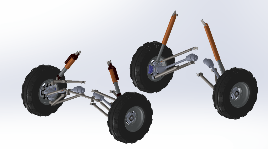
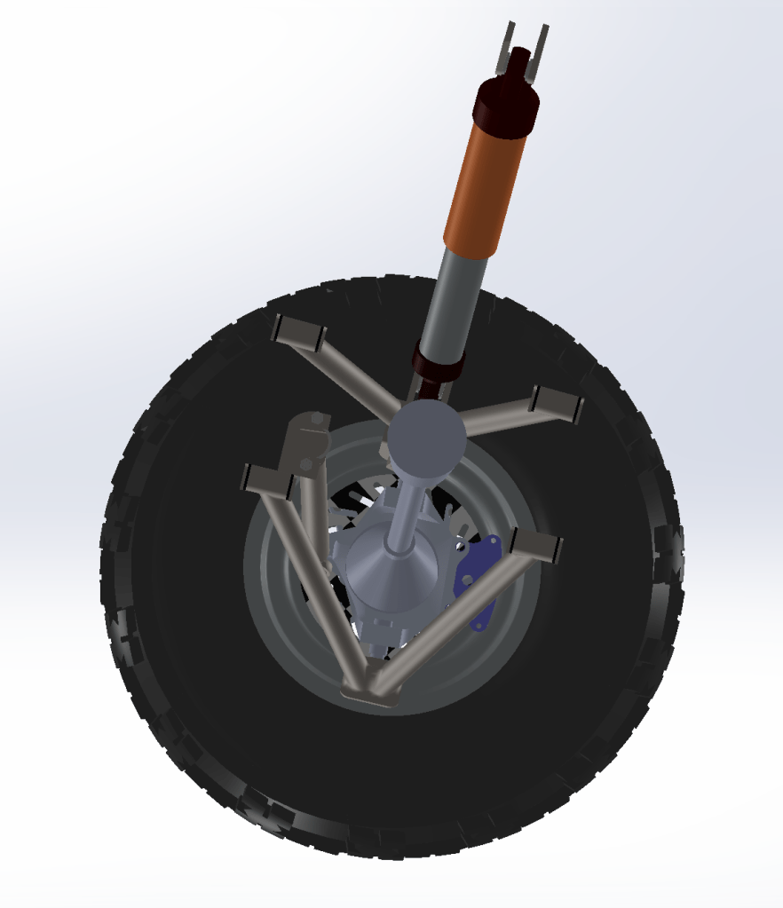
As the 2024-2025 Suspension Lead, I designed the constraining geometry behind the suspension and brakes systems. The suspension prioritizes strength-to-weight ratio, while working around the chassis and powertrain requirements.
My self-chosen design objectives were to maintain minimal bump steer and decrease our turning radius, while moving to a neutral Ackerman setup with increased load cases.
The Method
Lotus SHARK
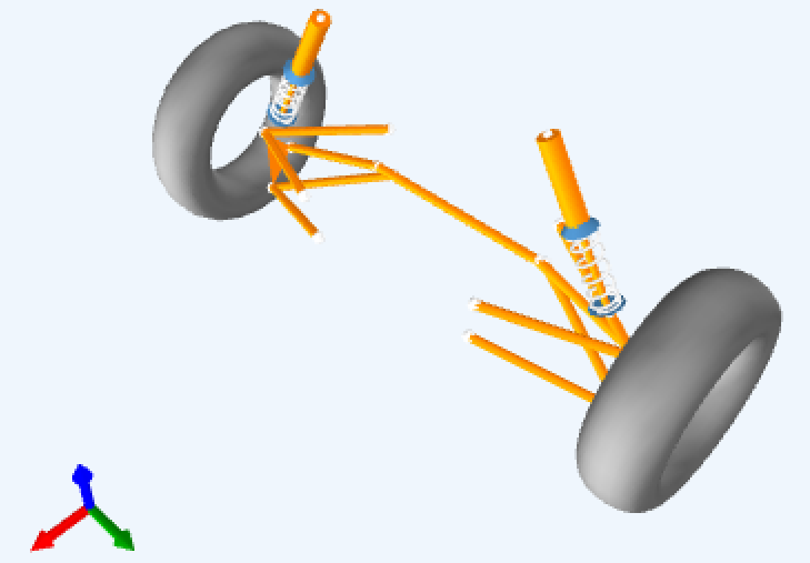
My initial work was done using a kinematics software called Lotus SHARK. Lotus SHARK takes an array of rotation points and performs kinematic analysis using them, outputting results through bump, roll, and steering modules. Most design work and major changes are done in Lotus, as it allows for the easiest iteration.

Optimum Kinematics
Further work was done using a second kinematics software called Optimum Kinematics. Optimum Kinematics is similar to Lotus, but can get a little more complex, allowing for combined bump, roll, and steering modules.
Design Changes
Neutral Ackerman
One major change I made from the previous year’s car was going to a neutral Ackerman setup. Ackerman steering describes the difference in the steering angles of the front tires, with positive Ackerman having the inside tire turn more and negative Ackerman having the outside wheel turn more. My goal was to get this as close to neutral as possible, where the wheels turn the same amount. This presents a good balance between slow maneuverability and faster cornering.
Positive Caster
Another major change was the introduction of caster. Caster is the angle of the steering axis from the side view. This also usually includes the angle of the shock and control arms, requiring chassis changes to match up mounting points.
Positive caster impacts the car in two main ways. It provides a returning force on the wheels, giving steering stability, especially at straights. It also results in more camber gain when steering, improving grip during cornering.
Other REsponsibilities
Team Lead
As the Suspension Lead, I was also responsible for assisting my 14 team members in the design cycle of their own projects. These include the welded control arms, the CNC’ed hubs and uprights, and the brakes system. In order to do so, I managed a Notion to oversee and organize the roughly 150 components that make up the projects. I also ran 2 weekly subteam meetings to maintain an aggressive timeline set by the Project Manager.
Executive Team
As a team lead, I was part of the executive team. We were responsible for setting the week-to-week schedule for the team, and worked together to ensure the team deadlines were reached across the team. We also planned competitions and team events, such as testing days, workshops, and non-engineering activities.
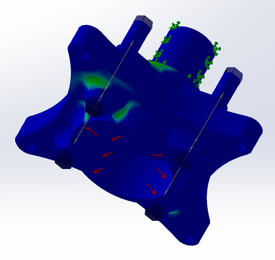
FEA
Every project on the suspension goes through rigorous FEA in order to be approved. As the Suspension Lead, I worked with the Chief Engineer to set load cases for the year, based on last year’s suspension performance and the projected new vehicle. Due to a estimated heavier, faster vehicle, we increased the previous loads by 20%. I worked with every member to teach them SolidWorks FEA and ensure proper methods. My goal for the entire subteam was to reach a Factor of Safety of 1.2, to account for load variations and the possibility of overloading.
CAM & CNC
There are three suspension projects that require CNCing. The front and rear uprights, and the hubs. I worked with these three team members to teach them Siemens NX CAM, and worked with the Manufacturing Lead to check and approve all CAM programs before machining. I also assisted with teaching them how to use the Haas Super Mini Mills and the Haas VF2 that the parts were made on.

Results
Turning Radius
The vehicle’s turning radius decreased from 13ft to 9ft compared to the previous year’s vehicle. This was measured at slow speed on dirt over three trials.
WEight increase
In total, the weight of designed components increased by 20.36%, slightly higher than the 20% increase in load cases.
Geometry Design Objectives
I was able to achieve minimal bump steer, with a maximum toe value of 0.75o during bump. I designed a slightly negative Ackerman setup, ranging from ~7.6o at straight to ~(-5.6o) at maximum steering. Finally, the caster was increased from 0o to 9.8o.
